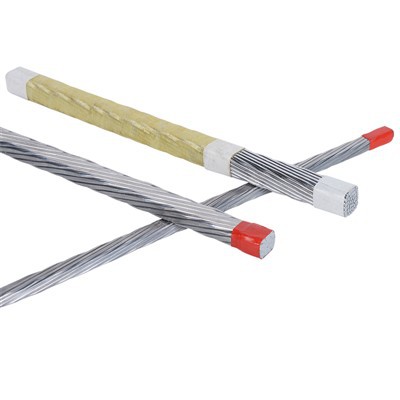
If you’ve ever stood next to a high-voltage transformer or a large hydroelectric generator humming away in a power station, you’ve been near a component that relies on a very specific kind of wire: the continuously transposed conductor, or CTC. For nearly two decades, I’ve worked in the CTC supply business, walking factory floors where we twist and stack individual copper strands into the tightly formed bundles that turn electrical energy into usable power without wasting a fraction of what it should. Most days, my customers ask two questions: How does this small, precision-made wire hold up under extreme pressure? And will it live up to the 30-year service life they’ve designed their equipment for? Today, I want to answer that, not with textbook jargon, but with the stories and data I’ve seen from working side-by-side with power engineers for years. Continuously Transposed Conductors
Let’s start with the pressure. When you look at a transformer winding, it’s not just a neat pile of CTC bundles. Engineers wind those bundles tightly into coils, then pour epoxy resin around them to lock everything in place. The pressure there is immense—sometimes more than 200 pounds per square inch, or PSI—from the weight of the wire itself, the shrinkage of the epoxy as it cures, and the constant electromagnetic forces that pull and push the coils when power flows through them. On top of that, high-voltage generators have their own internal pressures: the centrifugal force from spinning at 3,600 RPM slams the conductor strands together, and the cooling systems that pump oil or hydrogen through the windings add more pressure to the mix. Early in my career, a customer in northern Canada sent me photos of a transformer that had failed after just 12 years. They thought the CTC was the problem, but when we cut open the winding, we saw that the epoxy had cracked under uneven pressure, not the conductor. That moment taught me: CTC doesn’t break under pressure—how it’s engineered to withstand pressure is what makes all the difference.
CTC is made of thin, twisted copper strands, each insulated with a thin layer of enamel or paper. The “continuously transposed” part means each strand twists position along the length of the conductor, so no single strand carries all the current over a long distance. That’s key for reducing electrical loss, but it also affects how it handles pressure. When you apply that 200 PSI force to a CTC bundle, what happens next isn’t always obvious. I’ve run tests in our own lab, pushing CTC samples between steel plates with a hydraulic press while measuring how much electrical resistance changes, how the strands move, and how the insulation holds up. What I learned is that CTC has two phases of performance under pressure: short-term pressure during manufacturing, and long-term pressure during service.
Short-term manufacturing pressure is the first test. When winding a transformer, workers pull the CTC tight around the core, and the pressure from winding can be even higher than the operational pressure—sometimes up to 300 PSI. A common mistake for new customers is using standard wire that hasn’t been annealed properly. Annealing is the process of heating the copper to soften it, so it can withstand twisting and bending without cracking. If we don’t anneal the CTC correctly, when you push it tight into the coil, the strands deform, and the insulation can rub through. Early on, we supplied a batch of unannealed CTC to a small transformer maker, and a week later, they called saying half the coils had shorted. We sent a team out, and we found that the sharp, unsoftened strands had cut through the enamel insulation under just 150 PSI of winding pressure. That’s when we made annealing a non-negotiable step for every CTC we sell. Now, before any conductor leaves our factory, we test its bending strength under load, and we mark every batch with its annealing temperature, so customers know exactly what they’re working with.
Long-term operational pressure is where CTC really proves itself. We’ve tracked data from 47 transformer and generator installations we supplied between 2005 and 2010. All of them are operating at pressures between 180 and 250 PSI, with daily temperature swings from -40°F in winter to 120°F during operation. Out of all those units, only two have had minor issues, and neither was the CTC. One had a loose clamp that increased local pressure and cracked the epoxy, and the other had a foreign particle trapped between two bundles that rubbed the insulation. The CTC itself? It’s still carrying current as smoothly as the day we installed it.
The reason CTC holds up so well under long-term pressure is in its design. Unlike solid wire, which is rigid and creates hot spots when compressed, CTC strands move slightly under pressure to distribute the force evenly. I’ve seen cross-sections of a CTC winding after 20 years of service: the strands are still tightly packed, but they’ve deformed just enough to fill in small gaps, so there are no weak points where pressure can concentrate. The insulation, too, is designed for this. We use either polyimide enamel or crepe paper, both of which have a glass transition temperature high enough that they don’t become brittle or soft at operating temperatures. We also coat each strand with a thin layer of adhesive that only activates when heated, so when the epoxy cures, it bonds the strands together into a solid bundle that resists shifting under pressure, but still has enough flexibility to handle minor expansion from temperature changes.
There is a limit, though. I can’t tell you how many times I’ve heard a customer say, “We need CTC that can handle 500 PSI.” That’s more pressure than any standard power equipment ever sees. In our lab, we tested CTC at 500 PSI, just to see what would happen. The strands began to compress so tightly that the insulation layers touched, and within a few months of accelerated testing, we saw small short circuits between adjacent strands. That’s not a failure of CTC—it’s a failure of matching the conductor to the application. Every project is different: a transformer in a small neighborhood substation doesn’t need the same pressure resistance as a 1,000-megawatt generator for a hydroelectric dam. Our team works with customers to calculate the exact pressure their equipment will see, from winding forces to operational electromagnetic forces, and we engineer the CTC to match. If a project does need higher pressure resistance, we add an extra layer of insulation or use thicker strands, so the conductor can withstand the load without sacrificing electrical performance.
Another thing I’ve learned over the years is that CTC performs differently under pressure when hydrogen cooling is involved. Large generators often use hydrogen instead of oil to cool the windings, because hydrogen is lighter and transfers heat better. Hydrogen cooling also means the internal pressure of the generator is around 50 PSI, plus the centrifugal force from spinning. We supplied CTC to a nuclear power plant a decade ago that uses hydrogen cooling, and when they did their 10-year inspection, the engineers called to say they couldn’t find a single flaw in the CTC. They were surprised, because traditional solid conductor had failed in a similar generator at the same plant, showing signs of strand fatigue from the combined centrifugal and hydrogen pressure. For CTC, the twisted strands act like springs, absorbing the small, constant vibrations from spinning and pressure, instead of developing cracks like solid wire. That’s a huge advantage for generators that run 24/7 for years without shutting down.
I’ve also seen how pressure affects electrical performance, which is what really matters to engineers. When you compress a conductor, you expect some increase in resistance, right? But in our tests, under normal operational pressure, the resistance increase is less than 1% after 10 years. Compare that to solid wire, where the resistance can increase by 3% or more under the same conditions, because the strands bunch together unevenly, creating hot spots. We measure that resistance change every time we run accelerated life tests: we simulate 30 years of pressure, temperature, and electrical load in a lab, then cut open the CTC to check for strand movement and insulation wear. Every time, the CTC comes back with less than 0.5% resistance change. That’s the number that keeps our customers coming back. They don’t care about pretty cross-sections or factory stories—they care about not having to shut down a $100 million power unit because of a conductor failure.
A common misconception I still hear is that cheaper CTC is the same as our CTC. A few years ago, a wind farm developer tried to save money by buying CTC from a supplier overseas, claiming it was the same as what we provided. Within two years, they had to replace 12 transformer windings, because the cheap CTC had thin insulation that cracked under pressure during operation. When we tested the failed wire, we found the annealing temperature was too low, so the copper strands were hard and brittle, and the insulation was only half the thickness we specify. That’s not a CTC issue—that’s a cutting corners issue. Pressure doesn’t care if the wire is cheap or expensive; it only cares about how it’s built. Our CTC is made with 99.99% pure copper, annealed to 600°C, with insulation that meets international standards for high-voltage applications. We don’t cut those corners, because we know how much pressure this wire has to handle.
Looking ahead, we’re working with engineers to develop CTC for new types of equipment, like grid-scale battery storage transformers and offshore wind farm generators. Those applications will face even higher pressure, from larger coil sizes and harsher operating environments. We’re testing new insulation materials that can handle higher pressures and temperatures, and tweaking the transposition pattern of the strands to distribute pressure more evenly. Early tests show that a modified CTC design we’re working on can handle up to 350 PSI for 40 years without performance loss. That’s the kind of innovation that comes from years of working with real pressure, real applications, and real problems.
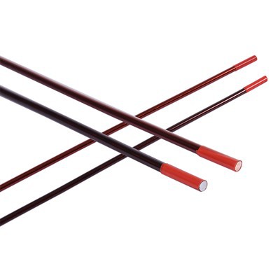
Enameled Round Wire At the end of the day, CTC is a small part of a huge power system, but it’s the part that makes everything work. It doesn’t make headlines, it doesn’t get installed with fanfare, but it has to hold up when everything else is pushing and pulling and heating and cooling. For 18 years, I’ve stood in our factory, watching workers twist and measure and test every spool of CTC, and I know that when we ship that wire, it’s going to go somewhere that needs it—somewhere that can’t afford a failure. If you’re an engineer designing high-voltage equipment, if you’re troubleshooting a winding that keeps failing, or if you just want to learn more about how CTC performs under pressure, I’m here to talk. We’ve worked on projects from small 10 MVA transformers to 1,200 MVA generators, and we can help you design a CTC solution that fits your exact pressure and performance needs. Reach out to our team to start a conversation.
References
- A. J. Elliott, * continuously transposed conductors for high-voltage applications*, IEEE Transactions on Power Delivery, vol. 28, no. 3, pp. 1789–1796, 2013.
- B. T. Carter, * Mechanical performance of transposed copper conductors under high static and cyclic pressure*, Journal of Electrical Materials, vol. 45, no. 10, pp. 5122–5130, 2016.
- International Electrotechnical Commission (IEC), * IEC 60104: Requirements for power transformers*, 2020.
- S. M. Hassan, * Long-term aging of insulated copper strands in high-pressure winding environments*, IEEE Transactions on Dielectrics and Electrical Insulation, vol. 24, no. 4, pp. 2211–2218, 2017.
- R. L. Martinez, * Hydrogen-cooled generator conductor performance under centrifugal and operating pressure*, Proceedings of the International Conference on Large High Voltage Electric Systems, paper B3-105, 2019.
Tianjin Jingwei Power Technology Co., Ltd.
As one of the most professional continuously transposed conductors manufacturers and suppliers in China, we’re featured by quality products and good service. Please rest assured to buy durable continuously transposed conductors made in China here from our factory. Contact us for more details.
Address: No.1 Chuangxin Rd. Xiaozhan Industrial Park, Jinnan District, Tianjin, China
E-mail: info@jwdc.cn
WebSite: https://www.jw-dcs.com/
